Traffic Signal Monitoring & Controller System - Complete DIY Tutorial & Code⭐ Featured
Both
Traffic Signal Monitoring & Controller System - Complete DIY Tutorial & Code
Contact for pricing· In Progress

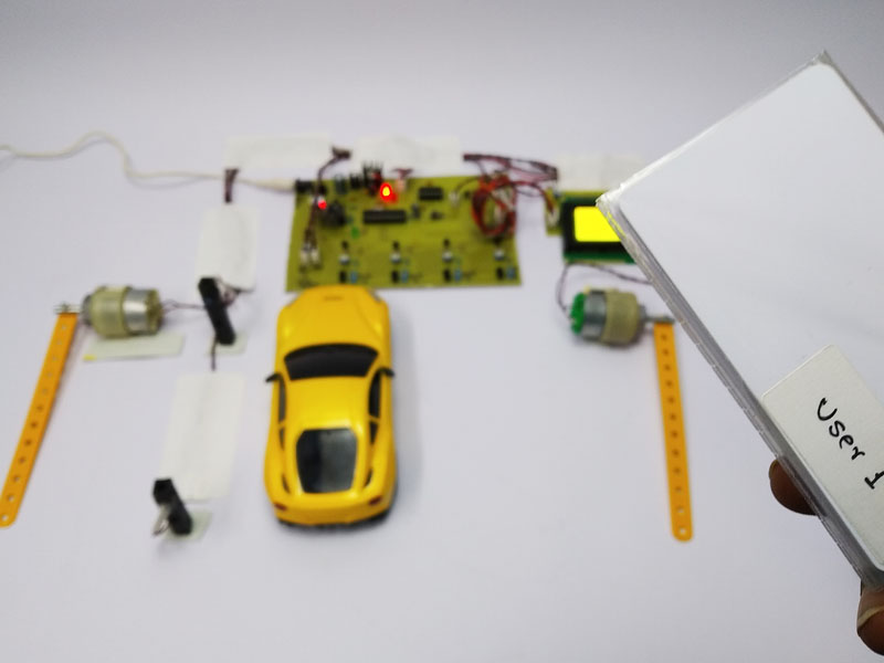
Introduction & Project Overview Fixed-timer traffic signals often cause unnecessary congestion because they don't adapt to actual traffic density at an intersection, leaving one lane waiting on a red light while another sits nearly empty. The Traffic Signal Monitoring & Controller System addresses this by using IR sensors to detect vehicle presence and density on each road at an intersection, then dynamically adjusting the green light duration for the lane with more traffic. The system also reports live traffic status to an IoT dashboard for city traffic management review. This project is an excellent Final Year Project (FYP) or semester project for Electrical, Computer Science, and Civil Engineering students, since it demonstrates a practical smart-city traffic optimization system combining sensor-based decision logic with cloud-based monitoring.

Contact Us About This Project

Working Process

Key Features & Functionality

Detects vehicle presence and density on each lane using IR sensors
Dynamically adjusts green light duration based on real-time traffic density per lane
Displays current signal status and countdown timer on a 16x2 LCD screen
Sends live traffic density data to an IoT dashboard (Blynk/ThingSpeak) for city monitoring
Includes a manual override mode for emergency vehicle priority
Cycles all four-way signal lights (Red, Yellow, Green) in proper sequence for each lane

Core Hardware Components Required

Arduino Mega 2560: Main microcontroller with enough I/O pins to manage a full four-way intersection
IR Infrared Obstacle Sensor (x4): Detects vehicle presence/density on each of the four approach lanes
Red, Yellow, Green LED Sets (x4): Represent the traffic signal lights for each lane
16x2 LCD Display with I2C Module: Displays current active lane and countdown timer
ESP8266 Wi-Fi Module: Sends live traffic density data to the cloud dashboard
Push Button: Manually triggers emergency vehicle priority override
Breadboard and Jumper Wires: For assembling and testing the complete four-lane circuit

Circuit Design & Pin Connections

Each of the four approach lanes has its own IR sensor to detect vehicle presence, along with a dedicated set of Red, Yellow, and Green LEDs representing that lane's signal. The Arduino Mega's larger number of I/O pins comfortably accommodates all four lanes simultaneously. The system logic reads all four IR sensors, determines which lane has the highest vehicle density, and extends that lane's green light duration accordingly while keeping the others red.

Complete Pin Connection Table

ComponentComponent PinMicrocontroller PinNotes / Description
Lane 1 IR SensorOUTPin 22Vehicle Detection Signal
Lane 2 IR SensorOUTPin 23Vehicle Detection Signal
Lane 3 IR SensorOUTPin 24Vehicle Detection Signal
Lane 4 IR SensorOUTPin 25Vehicle Detection Signal
Lane 1 LEDs (R/Y/G)AnodesPin 2, Pin 3, Pin 4Lane 1 Signal Lights
Lane 2 LEDs (R/Y/G)AnodesPin 5, Pin 6, Pin 7Lane 2 Signal Lights
Lane 3 LEDs (R/Y/G)AnodesPin 8, Pin 9, Pin 10Lane 3 Signal Lights
Lane 4 LEDs (R/Y/G)AnodesPin 11, Pin 12, Pin 13Lane 4 Signal Lights
16x2 LCD (I2C)SDA, SCLPin 20, Pin 21I2C Data Lines
Push Button (Emergency)One LegPin 26Manual Override Trigger
ESP8266TX, RXPin 18, Pin 19Serial Communication (Hardware Serial1)

Bill of Materials (BOM)

Product / ComponentQuantityLink
Arduino Mega 25601
IR Infrared Obstacle Sensor4
Red LED4
Yellow LED4
Green LED4
16x2 LCD Display with I2C Module1
ESP8266 Wi-Fi Module1
Push Button1
220Ω Resistor (LED current limiting)12
Breadboard and Jumper Wires1 set

Step-by-Step Assembly Tutorial

1.Step 1: Mount the Microcontroller Secure the Arduino Mega on a central base plate that represents your intersection model, positioned so wires can reach all four corners representing the four lanes.
2.Step 2: Connect the Power Rails Wire the Arduino's 5V and GND pins to a breadboard rail large enough to comfortably power all sixteen signal LEDs, four IR sensors, and the LCD.
3.Step 3: Wire the Primary Sensor Mount each of the four IR sensors at the "entry point" of its respective lane in your model and connect their outputs to Pins 22 through 25.
4.Step 4: Wire the Secondary Sensor (if applicable) If simulating variable traffic density more realistically, add a second IR sensor further back on each lane and combine both readings in software for a density score per lane.
5.Step 5: Setup the Communication Module Connect the ESP8266 module to the Arduino Mega's hardware Serial1 pins (Pin 18/19), which avoids the timing conflicts that SoftwareSerial can cause with four simultaneous LED sequences.
6.Step 6: Connect Output Displays Wire the 16x2 I2C LCD to Pin 20 (SDA) and Pin 21 (SCL) so it can show which lane currently has the green light and the remaining countdown time.
7.Step 7: Wire up the Buzzers/Alarms Connect the emergency override push button to Pin 26 so an operator can instantly force a green light on a specific lane for an approaching emergency vehicle.
8.Step 8: Double-Check for Short Circuits Carefully verify each LED has its own current-limiting resistor and that no two LED anode wires are accidentally connected to the same pin.
9.Step 9: Connect the USB Cable and Power Up Connect the Arduino Mega to your computer via USB, confirm it powers on correctly, and open the Arduino IDE ready to upload the four-lane control logic.
  1. Step 10: Final Assembly Check and Testing Block one lane's IR sensor to simulate heavy traffic and confirm that lane receives an extended green light duration while the LCD and cloud dashboard correctly reflect the change before finalizing your intersection model.

Arduino Source Code

// Dynamically manages a 4-way intersection based on real-time vehicle density
 
#include <Wire.h>
#include <LiquidCrystal_I2C.h>
 
// ----- IR Sensor Pins -----
const int irSensors[4] = {22, 23, 24, 25};
 
// ----- LED Pins: {Red, Yellow, Green} per lane -----
const int laneLEDs[4][3] = {
  {2, 3, 4},
  {5, 6, 7},
  {8, 9, 10},
  {11, 12, 13}
};
 
const int emergencyButton = 26;
 
LiquidCrystal_I2C lcd(0x27, 16, 2);
 
const int baseGreenTime = 5000;   // Minimum green light duration (ms)
const int extraTimePerVehicle = 2000; // Extra green time per detected vehicle
 
void setup() {
  for (int i = 0; i < 4; i++) {
	pinMode(irSensors[i], INPUT);
	for (int j = 0; j < 3; j++) {
  	pinMode(laneLEDs[i][j], OUTPUT);
	}
  }
  pinMode(emergencyButton, INPUT_PULLUP);
 
  lcd.init();
  lcd.backlight();
  lcd.print("Traffic Control");
 
  Serial1.begin(9600); // Hardware serial to ESP8266
  Serial.begin(9600);
  delay(1500);
  allRed();
}
 
void loop() {
  // Check for emergency override first
  if (digitalRead(emergencyButton) == LOW) {
	handleEmergency();
	return;
  }
 
  // Cycle through each lane based on detected density
  for (int lane = 0; lane < 4; lane++) {
	int density = readLaneDensity(lane);
	int greenDuration = baseGreenTime + (density * extraTimePerVehicle);
 
	runLaneCycle(lane, greenDuration);
	sendToCloud(lane, density);
  }
}
 
// Reads how many times the IR sensor detects a vehicle over a short sampling window
int readLaneDensity(int lane) {
  int count = 0;
  for (int i = 0; i < 5; i++) {
	if (digitalRead(irSensors[lane]) == LOW) count++;
	delay(100);
  }
  return count;
}
 
// Runs the full Red -> Green -> Yellow -> Red cycle for one lane
void runLaneCycle(int activeLane, int greenDuration) {
  allRed();
 
  digitalWrite(laneLEDs[activeLane][0], LOW);  // Turn off Red
  digitalWrite(laneLEDs[activeLane][2], HIGH); // Turn on Green
 
  lcd.clear();
  lcd.setCursor(0, 0);
  lcd.print("Lane " + String(activeLane + 1) + ": GREEN");
  delay(greenDuration);
 
  digitalWrite(laneLEDs[activeLane][2], LOW);  // Turn off Green
  digitalWrite(laneLEDs[activeLane][1], HIGH); // Turn on Yellow
  delay(2000);
  digitalWrite(laneLEDs[activeLane][1], LOW);  // Turn off Yellow
 
  allRed();
}
 
// Sets every lane's signal to Red as the default safe state
void allRed() {
  for (int i = 0; i < 4; i++) {
	digitalWrite(laneLEDs[i][0], HIGH); // Red ON
	digitalWrite(laneLEDs[i][1], LOW);  // Yellow OFF
	digitalWrite(laneLEDs[i][2], LOW);  // Green OFF
  }
}
 
// Immediately grants green to a manually selected emergency lane (Lane 1 as default)
void handleEmergency() {
  lcd.clear();
  lcd.print("EMERGENCY MODE");
  runLaneCycle(0, 8000); // Default emergency priority lane; customize as needed
}
 
// Sends the current lane and its detected density to the cloud dashboard
void sendToCloud(int lane, int density) {
  Serial1.print("Lane"); Serial1.print(lane + 1);
  Serial1.print(":"); Serial1.println(density); // ESP8266 forwards this to ThingSpeak/Blynk
}
 

Questions, Custom Pricing, or Requests

Want this project customized, a quote for your budget, help understanding a feature, or anything else related to it? Send us a message.

Prefer to talk? Call or WhatsApp us at +92 3176572690